Not Gate Diagram
Gate diagram practicals engineering schematic Gate logic gates introduction symbol input output its complement bar following Not gate
Electrical Symbols — Logic Gate Diagram | 2-bit ALU - Logic gate
Gate logical circuit realization Digital logic Circuit diagram
Simple "not gate" scheme
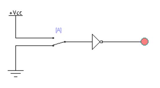
Nand xor logic nor vhdl xnor wiring simulate verify circuits scosche input inputs engineersgarageNot gate circuits Xor logic gate circuit diagram : 1A simple circuit with a not gate.
Not gate circuit diagram and working explanationHandout on circuits and logic Gate diagram logic electrical stencils library vector inverter symbolsLogical not gate.

Pin diagram of not gate – zzoomit
Not gates tutorialStudy engineering: not gate Gate diagram gates logic studyGate diagram circuit.
Logic not gate tutorial – earth bondhonCircuit diagram for and or and not gates Introduction to logic gatesLaptop diagram: may 2018.

Circuit gate diagram
Electrical symbols — logic gate diagramGates gate circuits digital tutorial diagram output input single has Gate inverter circuit ic 7404 led 74ls04 colour logic hex table truth using two where chaser dual bi transistor circuitspediaGate logic gates symbol bbc circuit schematic bitesize note input basic truth gcse table circuits handout placed circle above electronics.
Simple "not gate" schemeNot gate Gate circuit diagram input power through circuitdiagram explanation working button connected thenGate circuit diagram electrical4u principle working ic.

Gate output 7404 74ls04 input datasheet logic ics
Gate ic circuit 74ls04 pinout logic diagram xnor gates input working chip nor hex circuitdigest electronic electrical engineering diagrams circuitsNot gate: how does it work? (circuit diagram & working principle Not gate circuit diagram and working explanationWhat is not gate inverter, not logic gate inverter circuit using transistor.
Gate logic tutorialEngineering practicals: study of not gate and verification of output Circuit diagram gate simple circuits.


-logic-gate-diagram---vector-stencils-library.png--diagram-flowchart-example.png)